Commissioning a zoned heating system: the installer’s checklist
Commissioning is when a well-designed system becomes a system that works. Skip a check today and you get a call in mid-winter. Here is our checklist, in five stages.
Commissioning a zoned heating system is a job that tends to get squeezed: the site is running late, the client wants heat, “you can see straight away if it works”. You can’t. Many faults in a zoned system don’t show on day one: an actuator wired to the wrong zone, a sensor reading a degree low, a safety device never tested. They show in January, with a phone call.
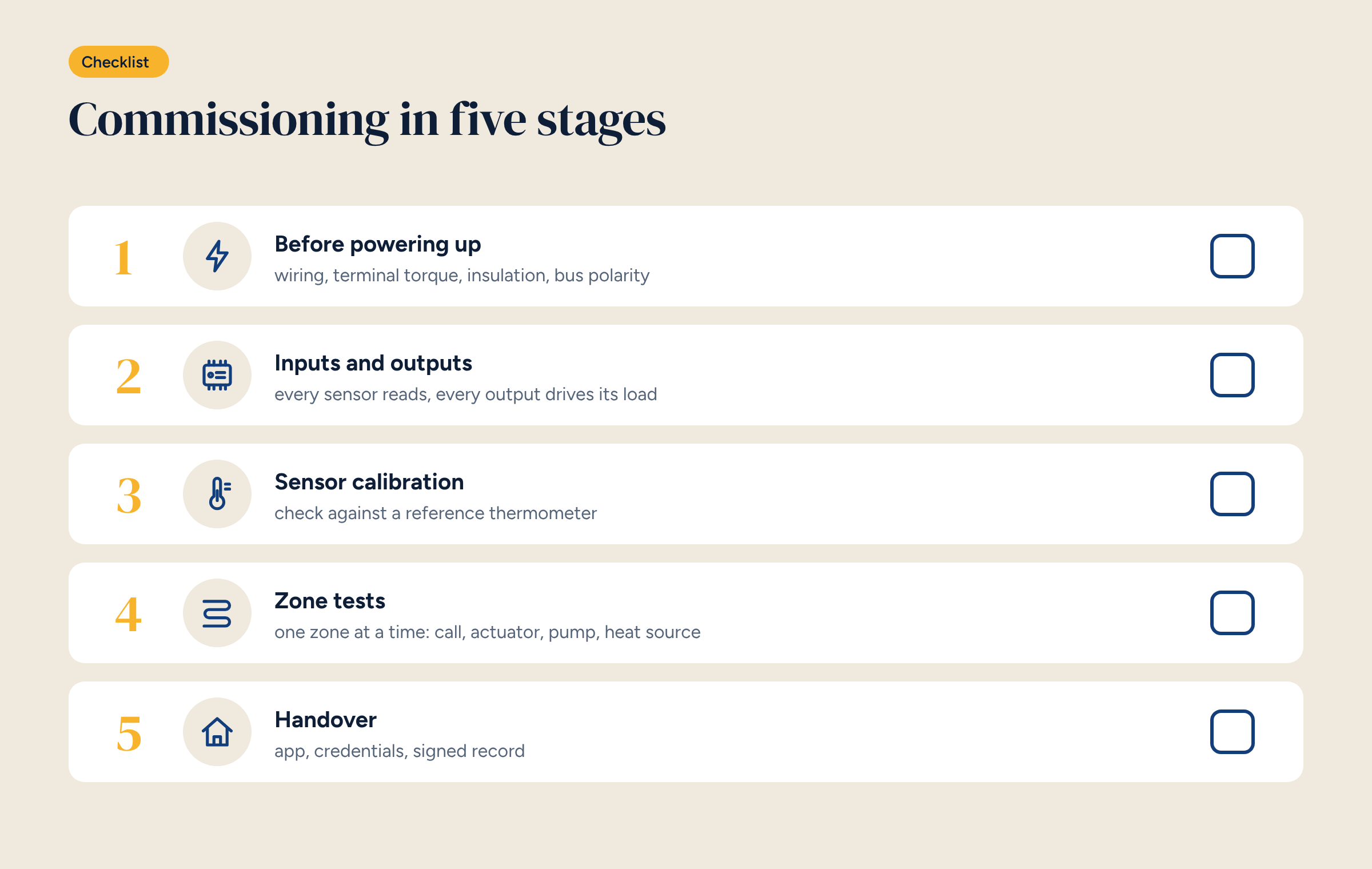
That’s why we use a checklist, always the same, in five stages. We share it here for installers working with Brick, but this underfloor heating commissioning checklist applies to any zone control system.
Commissioning in five stages: before power-up, inputs and outputs, sensor calibration, zone tests, handover.
First of all: the paperwork
Commissioning starts at the desk, not on site. Before going to site you need:
the panel wiring diagram, updated with any changes already known;
the zone list, with each zone’s manifold loops, rooms, sensors and actuators;
the design data: flow temperature, starting heating curve, safety limits;
the register maps of any Modbus devices;
a commissioning record form to fill in.
With these documents, every test has a reference. Without them, you end up testing “by eye”.
Stage 1: before power-up
With the panel dead, check the things that could cause damage at switch-on if wrong.
Wiring matches the diagram: every wire on its terminal, numbering legible.
Tightness: screw terminals are checked one by one. A loose terminal is the most common cause of intermittent faults.
Insulation and continuity of power and earth circuits.
Bus polarity: A and B on RS-485, KNX bus polarity, termination resistors only at the two ends of the line.
Power supply and actuator voltages consistent with the installed components: a 24 V actuator connected to 230 V fails instantly.
Only then apply power, first to the controller and then to the loads, one breaker at a time.
Stage 2: inputs and outputs
With the controller on, check that every input reads and every output drives its load.
Every sensor shows a plausible value: room sensors around room temperature, the outdoor sensor close to the real figure, the flow sensor consistent with the pipe.
Every contact changes state when operated: heat source demand, alarms, zone thermostats where present.
Every output drives the right load: activate an actuator from the controller and check on the manifold that the right one moves.
Analogue outputs: drive the mixing valve to 0, 5 and 10 V and check stroke and direction, as in the article on three-way valves.
Bus devices respond: correct addresses, sensible readings.
This is usually the longest stage, and the one where most labelling mistakes come to light.
Stage 3: sensor calibration
A sensor can work and still read wrongly. Compare each sensor with a reference thermometer, in the same position, after a few minutes to settle.
A difference of up to half a degree is normal and is corrected with an offset in the controller.
A difference of several degrees points to a problem: wrong sensor, wrong position, faulty connection.
Wireless sensors are also checked for signal and battery: a sensor with a weak signal on site will be worse once the furniture is in.
The flow sensor deserves extra attention: it must be in contact with the pipe, with thermal paste, and insulated. An uninsulated strap-on sensor reads two or three degrees low, and weather compensation suffers for ever.
Stage 4: zone tests
Now test the system as a whole, one zone at a time.
Force the zone’s call for heat, from the controller or by raising the set point.
Check that the right actuator opens, and only that one.
Check that the circuit pump starts and the heat demand reaches the heat source.
Check that the flow temperature reaches its target and stays stable.
Remove the call and check that everything stops, with the expected delays.
Then test the safety functions: the flow high-limit thermostat, by lowering its setting; frost protection; heating and cooling interlocks if the system also cools. A safety device never tested is one you don’t know works.
Finally test the edge cases: all zones at once, no zones, a sensor disconnected. The controller must respond safely and send an alert.
Stage 5: handover
Handover is not a bureaucratic detail: it is when the system passes to the client.
Set the zone schedules with the client, to suit their routines, and the starting heating curve.
Show the app: how to change a temperature, how to switch from Comfort to Eco, where to find consumption.
Hand over personal credentials and the access list, as set out in the minimum security rules.
Hand over the updated diagram, with a copy left in the panel, and the configuration export.
Sign the commissioning record, with the outcome of every test.
The most common mistakes
In our experience, four mistakes come up more than any others during commissioning.
Zones swapped between manifold and sensors, discovered only when the client complains that the bedroom warms up when they turn up the living room.
Sensor offsets forgotten, so the whole system runs half a degree warmer than it needs to.
Safety devices left untested, because “they’re new, they work”.
No commissioning record, leaving the client and the next installer with no trace of what was checked.
All four are avoided with the checklist, actually filled in rather than done from memory.
After handover
The checklist ends with an appointment: a review of the charts two or three weeks later. That is when you fine-tune the curve, hysteresis and schedules with real data, and when the client asks the questions they didn’t know they had on handover day.