From panel to data

The three-way mixing valve decides the temperature of the water going into the floor. Oversize it and the flow temperature hunts; undersize it and the floor won’t heat. Here is how to choose it and bring it into the panel.
In the guide to underfloor heating control we saw that the three-way mixing valve is the first link in the chain: it takes hot water from the heat source, blends it with water returning from the floor, and sends the right temperature to the loops. A 3-way mixing valve for underfloor heating is a simple component, yet it is often chosen or wired wrongly, and the consequences show up for years.
This article is for anyone who has to specify one on a project or fit one on site, whatever the brand.
Three-way valves are used in two ways that look the same but do opposite jobs.
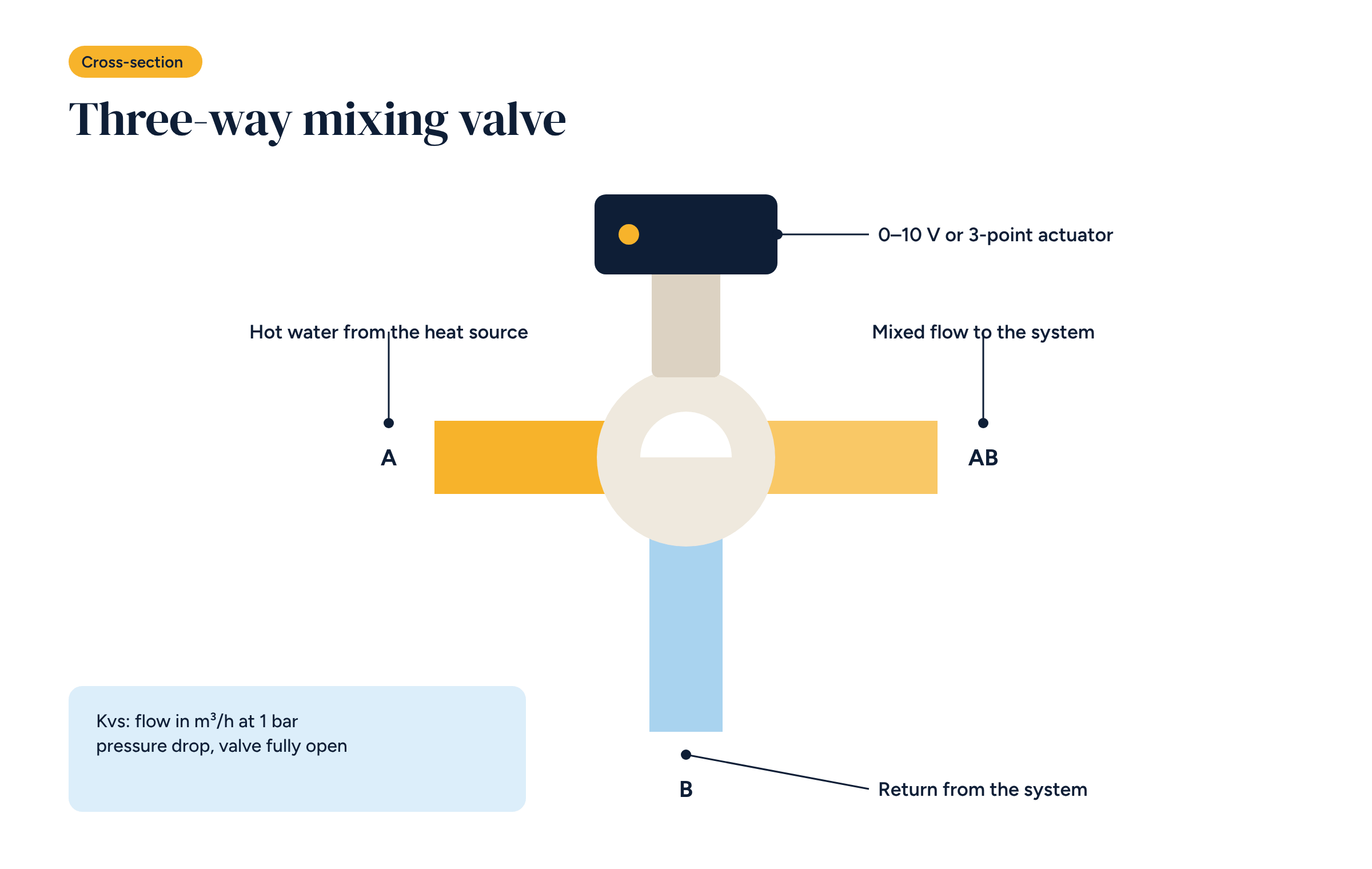
Mixing. Two inlets and one outlet. Hot water (port A) and return water (port B) come in, mixed water (port AB) goes out. Opening port A more warms the flow; opening port B more cools it. This is the typical case for an underfloor circuit fed by a boiler.
Diverting. One inlet and two outlets. Water enters at AB and leaves through A or B, or partly through both. It is used to send water to one of two loads, for example the heating circuit or the hot water cylinder, or as a bypass for a terminal unit.
Many valves can be fitted either way, but not all: the manufacturer states which configuration is allowed. Fitting a mixing valve as a diverter, or vice versa, can cause noise, leakage across the seat and unstable control.
The figure that decides the valve size is Kvs: the flow of water, in cubic metres per hour, that passes through the fully open valve with a pressure drop of 1 bar. The higher the Kvs, the bigger the valve.
Flow, Kvs and pressure drop are related by:
Δp [bar] = (Q / Kvs)²
where Q is the flow in m³/h. Pipe diameter says nothing about the right Kvs: a valve with connections matching the pipes is almost always too big.
An underfloor circuit has to deliver 10 kW with a 5 °C difference between flow and return.
A valve with Kvs 10 or 16, chosen “because the connections fit”, would nearly always work barely open: a small movement of the actuator would change the temperature a lot, and the flow temperature would hunt.
The valve is moved by an actuator. There are two common types.
3-point. It has two commands: open and close. The controller drives it with pulses of varying length. It is simple and cheap, but the controller never knows the valve position for sure, unless it runs the full stroke again.
Modulating 0–10 V. It receives a continuous signal: 0 V valve closed, 10 V valve open, values in between for intermediate positions. Many models also return a position signal. It is the best choice for weather compensation, because the position is always known and the controller can use proportional-integral control.
For both types, stroke time matters: the time the actuator takes to go from fully closed to fully open. For underfloor circuits, long stroke times of one to two minutes are fine, because the system is slow. Times that are too short make control jumpy.
In the panel, a modulating valve needs only a few conductors:
And one sensor: the flow sensor, downstream of the valve and pump, a few pipe diameters away from the valve so the water is already well mixed. Strapped to the pipe with thermal paste and insulated, or better still, in an immersion pocket.
Brick works with Siemens SAX, SAS and SSB modulating 0–10 V actuators and Siemens VXG three-way mixing valves, but the principle applies to any brand.
Two simple tests save a lot of phone calls. First: with the system off, drive the valve to 0 V, 5 V and 10 V and check that it travels its full stroke in the right direction. Second: with the system running, watch the flow temperature chart for an hour. If it swings by more than a degree around the set point, lengthen the integral time or check the Kvs. Set the heating curve afterwards, once the flow temperature is stable and predictable.
In the wiring diagrams of Brick’s configurations, the mixing valve, its actuator and the flow sensor are already drawn and numbered.