Open by choice

A heat pump with underfloor heating is the most efficient pairing there is, on one condition: the flow temperature must stay as low as possible. Let’s look at who should decide it, how to talk to the unit over Modbus, and which mistakes to avoid.
Heat pump weather compensation with underfloor heating is where the quality of control shows most clearly on the energy bill. A gas boiler works about as well with water at 40 or 50 °C, condensing aside. A heat pump does not: every extra degree it has to produce costs electricity.
So in a heat pump system, the question “who decides the flow temperature?” is not a technical detail. It is the question that decides how much the system uses.
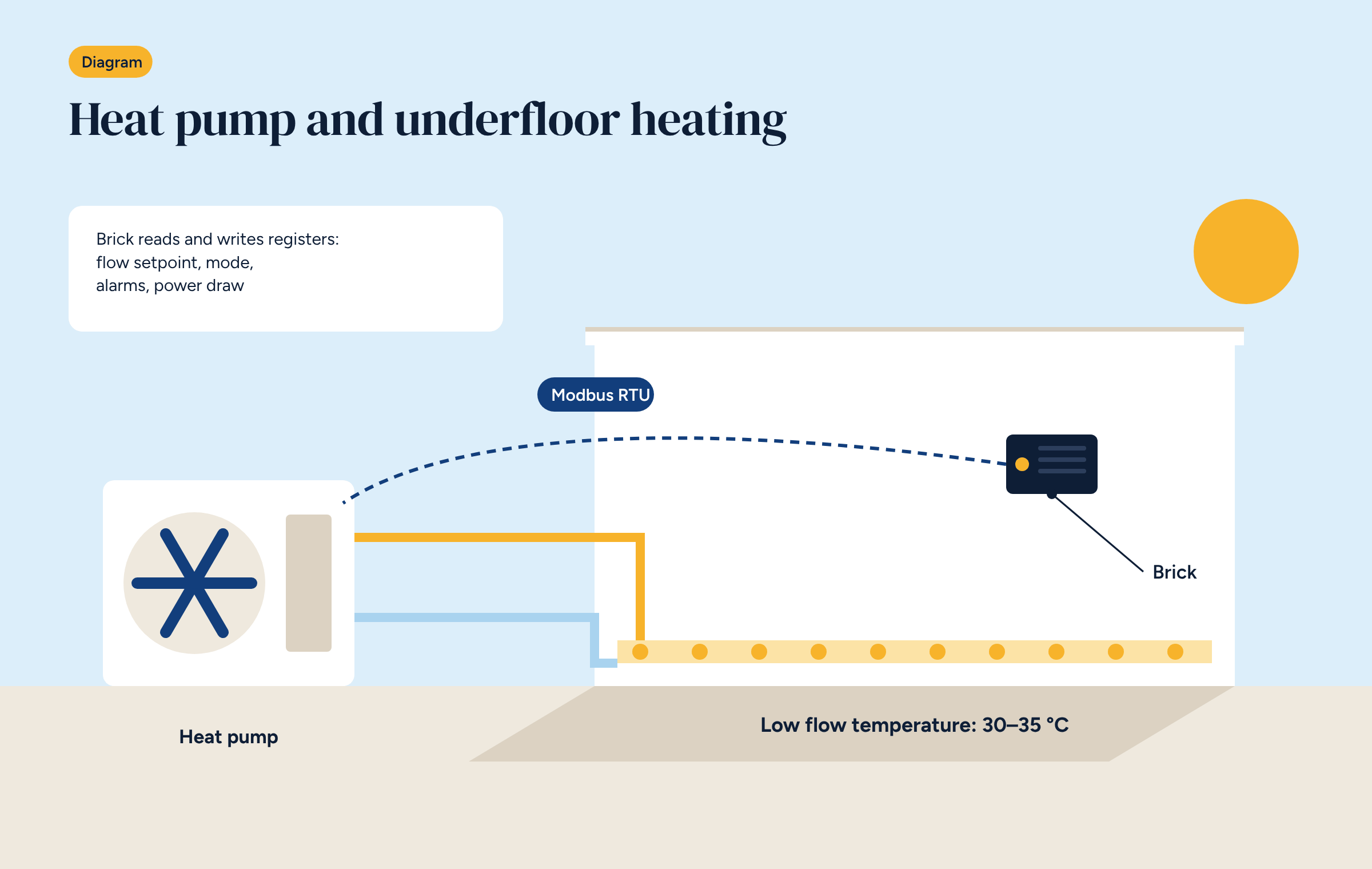
A heat pump moves heat from the outdoor air into the system water. The bigger the difference between the two temperatures, the harder the compressor has to work. Its efficiency, the COP, falls as the flow temperature rises.
In practice a rule of thumb is used: every degree off the flow temperature improves the COP by a few per cent, often around 2–3%. Going from 40 to 33 °C flow on a winter day can therefore be worth a significant saving, without touching anything else.
Underfloor heating is the ideal emitter precisely because its large surface heats well with water at 30–35 °C. But only if the controls let it work that way.
There are three ways to organise control.
The heat pump does everything. The unit has its own heating curve and outdoor sensor, and produces water at the temperature it calculates. The system controller only handles the zones. It is simple, but the heat pump knows nothing about the rooms: it follows the curve even when every zone is already up to temperature.
The controller sets the flow temperature. The controller calculates the flow temperature, using the heating curve plus a correction based on the zones, and writes it to the heat pump as a set point. The unit carries it out. It is the most efficient option, because the flow temperature takes account of what happens inside the building.
Contact control. The controller switches the heat pump on and off with a contact, and the unit works on its own curve. It is the minimum option, suited to units with no communication interface.
We recommend the second, where the unit allows it. But it needs reliable communication between controller and heat pump, almost always over Modbus.
Many heat pumps have a Modbus port, sometimes as standard, sometimes with an optional board. Through it the controller can:
The key document is the manufacturer’s register map, which gives the address, type and scaling of each value. As we saw in the article on protocols, Modbus is simple but unforgiving: an address off by one gives meaningless values.
To give an idea, a register map contains entries like these. This is a generic example, not a real unit:
Scaling is the most common trap: tenths of a degree, hundredths, sometimes signed values for sub-zero temperatures. Check it by reading a known value before writing anything.
Some units store set points in non-volatile memory that tolerates a limited number of writes. A controller that rewrites the set point every minute, even when it hasn’t changed, can wear it out in a few years.
The rule is simple: write only when the value actually changes, and with a tolerance, say half a degree. Then the set point changes a few dozen times a day, not thousands. This applies to every writable parameter, not just the flow temperature.
Many heat pumps are reversible, and in summer the same controller decides the chilled water temperature for the floor and fan coils. Here the logic is turned upside down: the lower limit is no longer about efficiency but about safety, because a floor that is too cold condenses moisture. The controller has to know the humidity in the rooms and keep the flow above the dew point, a subject we will cover in a dedicated article on underfloor cooling.
With a dedicated electricity meter on the heat pump and, if possible, a heat meter, you can calculate the real COP day by day. Plotted next to outdoor and flow temperatures, it shows straight away whether the controls are keeping the flow where it should be. The readings to collect are those in the article on the six readings in a plant room, and the method for the curve is in the article on weather compensation.
Brick’s configurations handle the heating and cooling source, whether a boiler, a chiller or a heat pump. With Modbus-equipped units, Brick reads the heat pump’s data and writes the flow set point calculated from the heating curve, corrected for the zones, while running the underfloor heating and fan coils. It is the same system described in the guide to underfloor heating control, with a unit that uses less the better it is controlled.
Configurations C0 and D0 handle heating and cooling sources, including over Modbus, together with underfloor heating and fan coils. Compare them and download the diagrams.